The 1-wire bus is a useful communications system for the Arduino. It allows many 1-wire devices to be linked in parallel and then all connected to one single data pin on the Arduino. This is great as I/O pins are limited on your microcontroller, but devices are not, so therefore, you would soon run out of pins!
The issue is that there are no address sticky labels or markings on the devices, so to the human eye, they are the same. Internally however, they are allocated addresses programmed into their ROM. So when we are building our codes and circuits, we need to know which device has which address! To do this, we run a little code and watch the results on the Serial Monitor.
Connecting the circuit up as follows: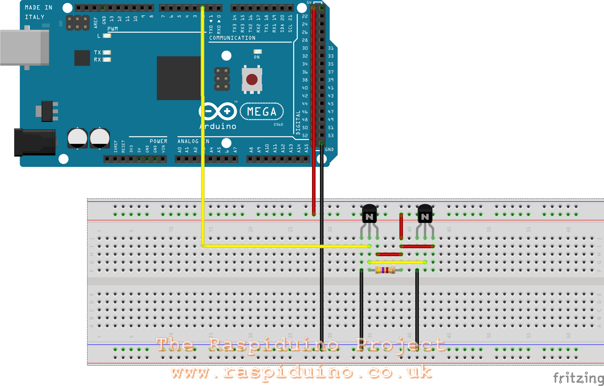
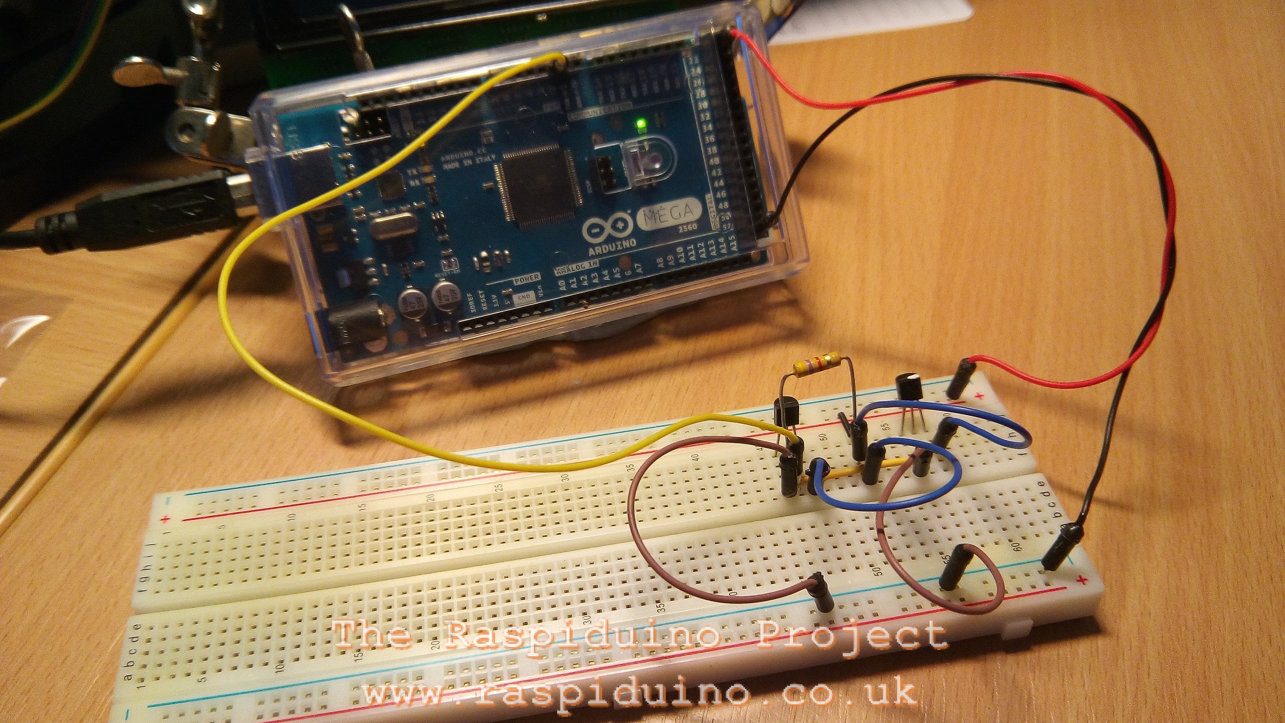
Multiple Dallas 1-Wire Connection
Running the code (at the bottom of this article), produces the following output on the serial monitor:
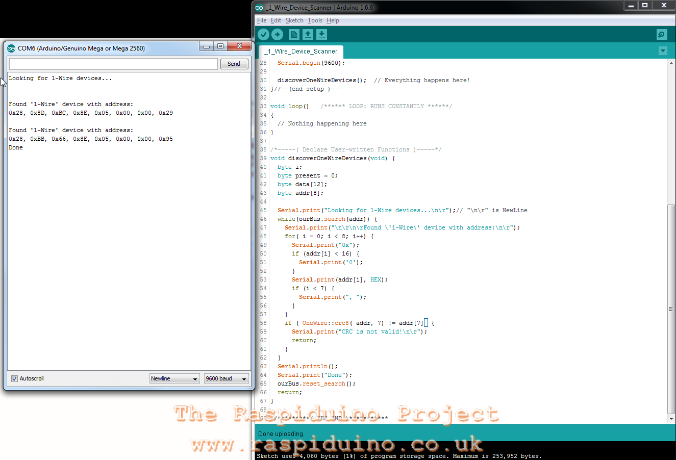
Can you spot a little problem?
Yup, which DS18B20 has which address?
To solve this, the easiest way is to tag each sensor and run the code with only one sensor attached at a time. Make a note of the address and somehow ID that sensor with that address. In my case, I have put a white paint mark on one sensor.
DS18B20 Datasheet can be found here…
Sensor with no white mark:
Looking for 1-Wire devices...

 Found '1-Wire' device with address:
 0x28, 0x8D, 0xBC, 0x8E, 0x05, 0x00, 0x00, 0x29
Done
Sensor with white mark:
Looking for 1-Wire devices...

 Found '1-Wire' device with address:
 0x28, 0xBB, 0x66, 0x8E, 0x05, 0x00, 0x00, 0x95
Done
Address Finder Code:
/*
Sketch used to find 1-wire devices and their addresses / serial number and then display on Serial Monitor.
Based on example at: http://www.hacktronics.com/Tutorials/arduino-1-wire-address-finder.html
Connections:
 DS18B20 Pinout (Left to Right, pins down, flat side toward you)
 - Left = Ground
 - Center = Signal (Pin 2): (with 3.3K to 4.7K resistor to +5 or 3.3 )
 - Right = +5 or +3.3 V
 */

/*-----( Import needed libraries )-----*/
#include <OneWire.h>

/*-----( Declare Constants and Pin Numbers )-----*/
#define SENSOR_PIN 2 // Any pin 2 to 12 (not 13) and A0 to A5

/*-----( Declare objects )-----*/
OneWire ourBus(SENSOR_PIN); // Create a 1-wire object

void setup() {
  Serial.begin(9600);
  discoverOneWireDevices(); // Everything happens here!
}//--(end setup )---

void loop() {
 // Nothing happening here
}

/*-----( Declare User-written Functions )-----*/
void discoverOneWireDevices(void) {
  byte i;
  byte present = 0;
  byte data[12];
  byte addr[8];

  Serial.print("Looking for 1-Wire devices...\n\r");// "\n\r" is NewLine
  while(ourBus.search(addr)) {
    Serial.print("\n\r\n\rFound \'1-Wire\' device with address:\n\r");
    for( i = 0; i < 8; i++) {
      Serial.print("0x");
      if (addr[i] < 16) {
        Serial.print('0');
      }
      Serial.print(addr[i], HEX);
      if (i < 7) {
        Serial.print(", ");
      }
    }
    if ( OneWire::crc8( addr, 7) != addr[7]) {
      Serial.print("CRC is not valid!\n\r");
    return;
    }
  }
  Serial.println();
  Serial.print("Done");
  ourBus.reset_search();
  return;
}

//*********( THE END )***********